The open source Process Design Kit from Google and SkyWater Technology Foundry, SKY130, in addition to open tools such as OpenLane make it easier than ever to get started in IC design without signing restrictive licenses/non disclosure agreements for PDKs or paying a small fortune for development tools.
To actually manufacture your design and get a chip in your hands to test is even more difficult; a traditional full mask set for a 180nm process can cost roughly $100,000 dollars, and even splitting space with other projects on the same wafer still costs roughly $9,750 per project (using efabless chipignite’s MPW). Making open source silicon even more accessible, Tiny Tapeout stitches many designs onto one project, bringing the cost down to $50 per 160 x 100 um tile and $100 for a development PCB with the IC containing everyone’s designs!
This blog is about my submission I put together in a couple days for the demoscene competition, which challenges designers to create an audiovisual demo on a small area (two tiles) via direct VGA PMOD signals. I am very excited to get a dev board with a chip back in about nine months to test my design (and every other tiny tapeout 8 submission). Also, since tiny tapeout recently began supporting analog designs, I am looking forward to reimplementing and tape-out some mixed-signal design projects I did in college.
Check out a simulation of the chip output and images of the final GDS, plus background, analysis and demos for the approximate multiplier I used!
Table of Contents
Open Table of Contents
Demoscene Competition
Like how the “Can it run DOOM” meme pushes the capability of constrained devices to run the video game (on anything from a graphing calculator to the IKEA TRÅDFRI Lamp), the home computer demoscene challenges people to overcome hardware limitations and produce their own custom adiovisual demos.
The Tiny Tapeout demoscene competition is similar, except you design your own ASIC hardware in a tiny area instead of using a computer! No CPU, no GPU, no RAM, just racing the beam, straight to VGA 640x480@60Hz.
People submitted very incredible demos, all of which are posted in the overview page. Some include Drop by Renaldas Zioma, Warp by Sylvain Lefebvre (written with his own custom HDL, Silice), and Demo by a1k0n (Andy Sloane).
My Submission
Many years ago I saw some obfuscated c code in the shape of a donut that produced an ASCII render of a rotating donut and thought it was the coolest. I knew I wanted to make some type of 3d donut for this submission and landed on rendering circles to build it up.
As it turned out, the same person who made donut.c was also involved with the Tiny Tapeout competition; very helpful on discord and submitted a super cool hardware version of the rotating donut (2x2 tiles so twice as large as allotted by the competition).
Simulating Output
The VGA Playground was incredibly helpful to quickly iterate while working on my design. Instead of using Icarus Verilog locally and waiting nearly 5 minutes per frame to render after every change, I could see my video output in nearly real time! VGA Playground uses the much faster Verilator compiled to WASM to run directly from the browser.
One reason I love open-source: instead of dealing with setting up verilator locally, it was actually easier to clone the vga-playground repo and make a three line edit1 to send each frame over a websocket to a small python script I wrote that processed and saved each frame. I didn’t have to wait ages to get the video output!
Take a look at the final gif below (unfortunately I didn’t have time to optimize the flying particles and they were cut out)!
 VGA output with particles
DRUM (Dynamic Range Unbiased Multiplier)
The area of a hardware multiplier grows quadratically with the input bit-width, so in a project with area as the main design constraint and one that uses many multipliers to draw circles, it’s a good idea to try to optimize them.
The simplest optimization is to reduce the multiplier bitwidth: throw away a portion of the 10-bit input, square it, then shift the output to the required size. The issue here is that the introduced error strongly depends on the magnitude of our inputs. Say, for example, we have an 8-bit input and square only the top 4 bits, there is a…
- small effect for large numbers, i.e.
202 = 8'b1100_1010would get chopped to8'b1100_0000 = 192, giving an approximate square of36864instead of40804, an error of -9.7 percent. - much worse effect for smaller numbers, i.e.
26 = 8b'0001_1010would get chopped to8'b0001_0000 = 16, giving an approximate square of256instead of676, an error of -62 percent!
Also, by chopping the input, it and the result are always smaller which introduces a bias.
The percent error is plotted against each input value below for this method. The selected bits are highlighted (currently the most significant 4 bits). Try to click and drag the selection to see how the percent error changes, and take note of the shaded portion.
One thing to notice is that for the smaller example above, our 4-bit multiplier is only performing a 1-bit multiplication: the top three bits are wasted (always zero) for any input in the range 8b0001_0000 to 8'b0001_1111 = 16 to 31. What if, for inputs in this range, we used bits 1 to 4 as the input for the 4-bit multiplier instead of the most top four?
This is the basis of the Dynamic Range Unbiased Multiplier, which finds the most-significant 1 in the input, chooses the next k-1 bits (where k is the bitwidth of the internal multiplier), and un-biases the input by setting the least-significant bit to 1 (its expected value). It effectively shifts which bits are chosen based on the magnitude of the inputs, avoiding the previous issue of wasting bits.
The shaded portion in the diagram above represents the range of values for which the given selection is used in this method - you can see that it places a bound on the percent error of about 20% across the entire range of inputs and increases dynamic range (enabling the multiplication of small numbers).
Output Quality
The paper charts out the error for various values of K and demonstrates performance on image filtering, JPEG compression, and a perceptron classifier. While less quantitative, I like seeing the very obvious effects of DRUM and DRUM-less multipliers on drawing circle patterns.
The comparison is shown in the test pattern below with N = 10-bit inputs; the top row are DRUM dynamic selectors to K = 5, 6, and 7-bit internal multipliers while the bottom row only statically selects the middle bits for the K = 5, 6, and 7-bit multipliers (with the toggle-able error overlay representing a full 10-bit multiplier). The improved error for low magnitude values can be seen as a reduction in the flat section on the top, and higher resolution in the curves. The bias in the static section multiplier is clearly seen as a shift when toggling the overlay, compared to the centered DRUM outputs on the top row.
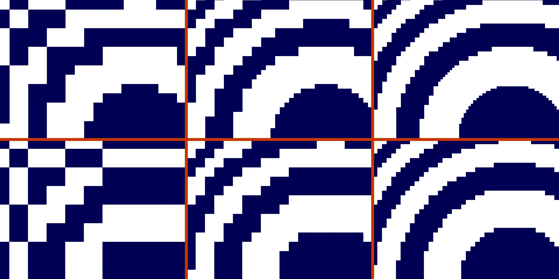 Test pattern with DRUM (top row, left to right N=10, K=4,5,6) and without DRUM (bottom row, left to right K=4,5,6)
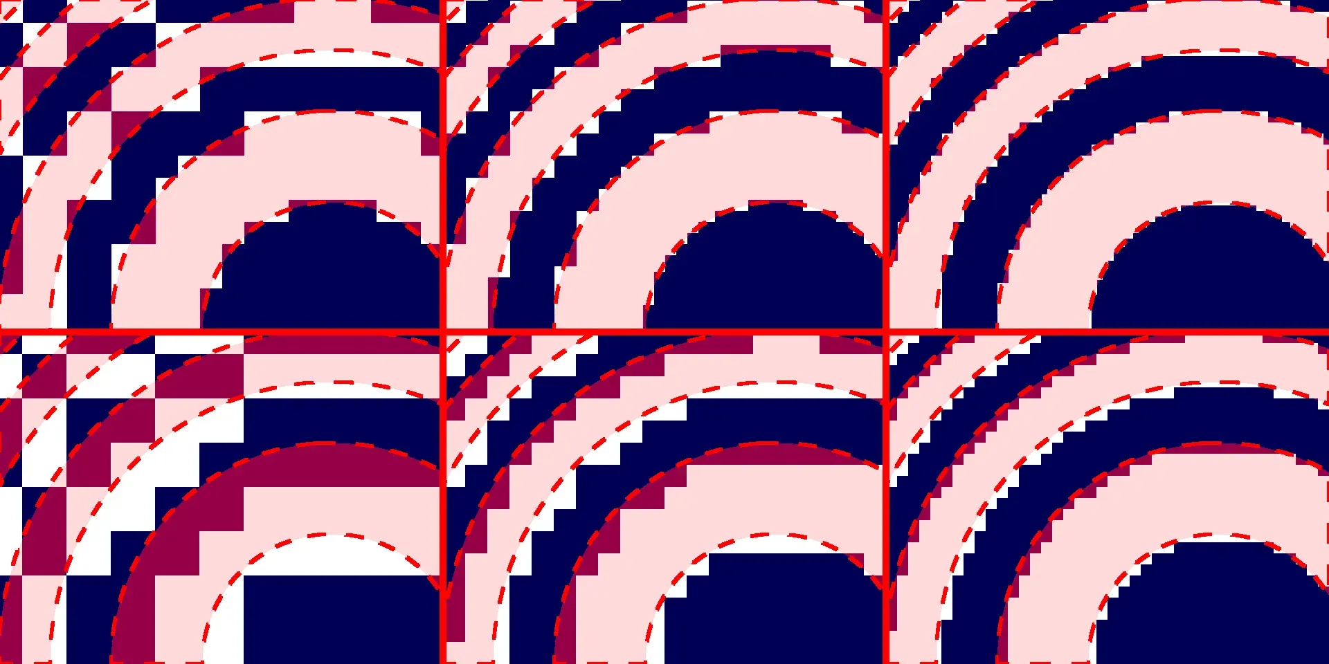 Test pattern with DRUM (top row, left to right N=10, K=4,5,6) and without DRUM (bottom row, left to right N=4,5,6), full 10-bit multiplier in red
PPA Comparison
Peeling back the curtain and looking at what the openlane flow does behind the hood, I created a custom tcl script along with some python to parse log outputs in order to analyze relevant performance metrics for various DRUM configurations and the full multiplier output.
The largest consideration in this project is area which is presented in the following plot. DRUM and full multipliers both scale roughly equally,2 with DRUM showing dramatically less error in the image above. For K = 5, 6, 7, the VGA output of which shown above, the area is only 44, 46, and 58 percent of a full 10-bit multiplier respectively but reduces error dramatically.
The reduction in error doesn’t come for free; the plots below demonstrate the cost associated with using DRUM instead of just a static k x k multiplier. Delay drastically increases as the critical path through the dynamic shifting logic becomes comparable to or much greater than the delay of the multiplier alone, decreasing at k = 9 and k = 10 since there is little to no shifting logic left.
A similar effect can be seen with the power increase. Static leakage power stayed roughly constant; the differences here are in internal and switching power. The tool reporting power, OpenSTA, “uses static power analysis based on propagated or annotated pin activities in
the circuit”. When a bit is switched in the input, it might switch the output of a connected gate, which in turn might switch the next gate and so on - all of which uses dynamic power and is traced by the tool. Now imagine switching one input bit: if that bit is more significant than the current leading one then the k biit selection changes to include that new leading one, possibly changing every input to the DRUM’s internal core multiplier (in addition to the dynamic power associated with the steering logic).
The next plots explore the effect of increasing the input size n for fixed k = 6, 7, 8, maintaining DRUM’s internal multiplier size while increasing steering logic.
Synthesis / PnR Sats
3181 total logic cells taking up 25873.6 square microns
Routing stats
| Utilisation (%) | Wire length (um) |
|---|---|
| 85.14 | 70895 |
Cell usage by Category
| Category | Cells | Count |
|---|---|---|
| Fill | decap fill | 1895 |
| Combo Logic | and4bb and4b and2b a21o a211o a31o a21oi o211a o21a o21ai a21bo and3b a311o o22a a22o a2bb2o o2bb2a o21bai or4b or3b o41a a2111oi o41ai a22oi o31a o22ai a211oi a221o a41o o32a a31oi o21ba a2111o or4bb a32o o211ai o31ai nor3b o2111a a221oi a311oi o311a a32oi o221a nand4b nand3b o221ai a2bb2oi o2bb2ai | 1122 |
| NOR | nor2 xnor2 nor3 nor4 | 633 |
| Tap | tapvpwrvgnd | 456 |
| OR | or2 or3 xor2 or4 | 416 |
| NAND | nand2 nand2b nand3 nand4 | 362 |
| AND | and2 and4 and3 a21boi | 231 |
| Buffer | buf clkbuf | 150 |
| Multiplexer | mux2 | 83 |
| Misc | dlymetal6s2s conb dlygate4sd1 dlymetal6s4s dlygate4sd3 | 82 |
| Inverter | inv | 79 |
| Flip Flops | dfxtp | 22 |
| Diode | diode | 1 |
Final GDS Renders
The following images were created by loading and filtering the output gds file with gdstk, similar to the Tiny Tapeout support tools. I created my own python script since the default image has no strict drawing order and doesn’t flatten cells, leading to randomized z-ordering (e.g. a polygon on a layer that would be manufactured below another polygon might randomly be drawn above it).
The minified image on the left shows the chip with no fill, decap, tap cells and no metal layers - with each standard cell (a cell implementing a logic gate or a flip-flop) outlined in red.
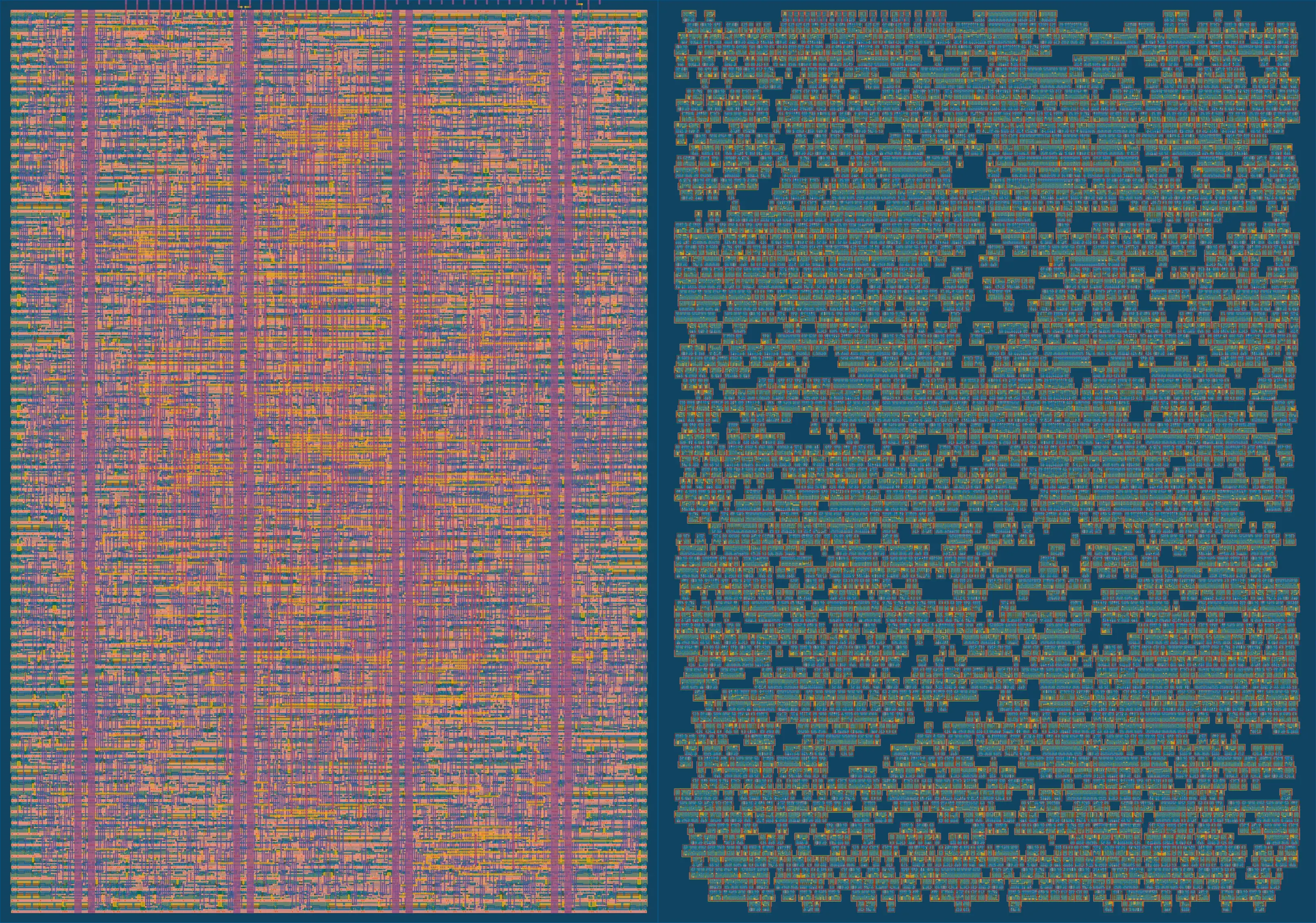 Full and minified images of the final GDS
Routing all the standard cells, connecting the inputs and outputs, is one of those NP-hard problems in chip design - you can see how hectic the final result is in the image on the left. An image of the original Pentium processor in a recent blog by Ken Shirriff shows what the three dimensional structure of the wires on multiple layers would look like on a manufactured chip under a microscope. To exaggerate the depth, the image on the right is in black and white, depicting higher metal layers as brighter. The full metal stackup shows the actual depth of each metal layer (metal layer 5 is reserved in Tiny Tapeout).
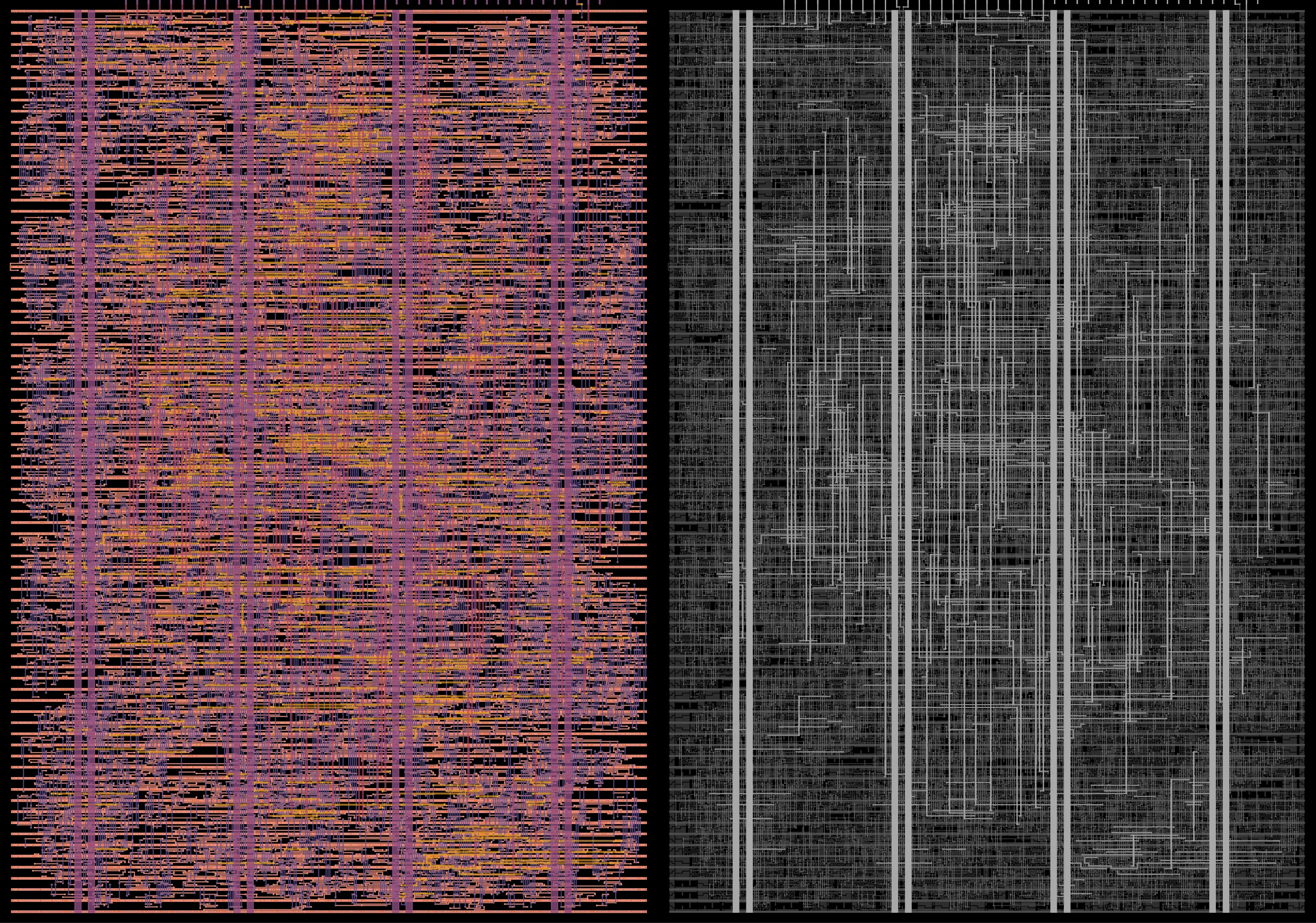 Metal layers and BW depth images of the final GDS
VGA IO
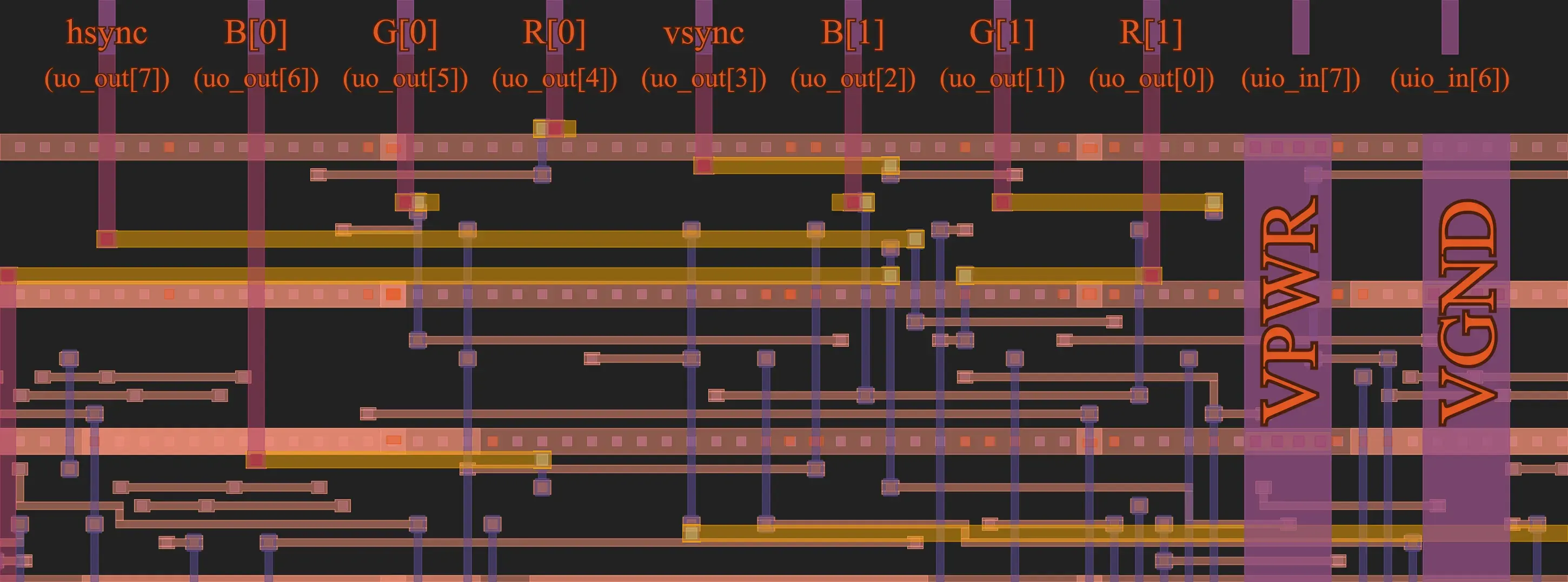 Labeled IO at the top of the cell and corresponding VGA signals
Footnotes
-
diff --git a/src/index.ts b/src/index.ts
index 7b16196..7c6eb68 100644
@@ -8,0 +9 @@ import { AudioPlayer } from './AudioPlayer';
+let webSocket = new WebSocket("ws://localhost:5000");
@@ -212,0 +214,2 @@ function animationFrame(now: number) {
+  webSocket.send(`${now}`)
+  webSocket.send(data)
My edit to
src/index.ts↩ -
One would expect DRUM area to consistently be greater than the full multiplier of size
ksince DRUM necessarily contains ak x kmultiplier plus more logic for selecting the dynamic shift amount. The variation in results might just be the randomness inherent in the ASIC EDA algorithms (they are approximating NP-hard problems after all). Openlane fixes the PRNG for each step for replicability; one future step could be running everything with different seeds and comparing means, mins, and maxes of the results. ↩